Electrical Grounding Standards and Key Grounding Parameters
Electrical grounding standards. 1. Scope: This standard specifies grounding requirements for electrical lines in the power systems of production and business units, including new construction, expansions, maintenance and repair, renovation, office areas, and employee dormitories. 2. Terms and definitions: Electrical systems use protective grounding, protective neutral grounding, repeated grounding, functional grounding, and other protection methods.
Electrical Grounding Standards
1. Scope:
This standard specifies grounding requirements for electrical lines in the power systems of production and business units, including new construction, expansions, maintenance and repair, renovation, office areas, and employee dormitories.
2. Terms and definitions:
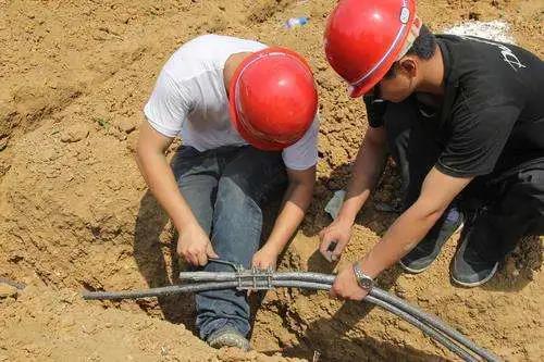
Electrical systems use protection methods including protective grounding, protective neutral grounding, repeated grounding, and functional grounding. A good electrical connection between a part of electrical equipment and earth is called grounding. A metal conductor or group of metal conductors in direct contact with the soil is called a grounding electrode; a metal conductor connecting the part of electrical equipment that must be grounded to the grounding electrode is called a grounding conductor; the grounding electrode and grounding conductor together are called a grounding system.
3. Grounding concepts and types:
(1) Lightning-protection grounding: Grounding intended to direct lightning rapidly into the earth and prevent lightning damage. If the grounding system of a lightning-protection device is combined with the functional grounding system of telecommunications equipment in one common grounding grid, the grounding resistance must meet the minimum-value requirement.
(2) AC functional grounding: Connecting a point in the power system to earth through a metallic connection, either directly or through special equipment. Functional grounding mainly refers to grounding the transformer neutral point or neutral conductor (N conductor).
The N conductor must be an insulated copper conductor. Auxiliary equipotential bonding terminals are used in power distribution; they are generally located inside enclosures or cabinets. Note that these terminals must not be exposed; they must not be mixed with other grounding systems, such as DC grounding, shield grounding, or antistatic grounding; and they must not be connected to the PE conductor.
(3) Protective safety grounding: A good metallic connection between the non-current-carrying metal parts of electrical equipment and the grounding electrode. This means connecting electrical equipment inside a building, as well as nearby metal structures, to the PE conductor. It is strictly prohibited to connect the PE conductor to the N conductor.
(4) DC grounding: To ensure the accuracy and stability of electronic equipment, a stable reference potential is needed in addition to a stable power supply. An insulated copper lead with a relatively large cross-sectional area may be used, with one end connected directly to the reference potential and the other end providing DC grounding for electronic equipment.
(5) Antistatic grounding: Grounding used to prevent static electricity generated in the dry environment of computer rooms in intelligent buildings from interfering with electronic equipment is called antistatic grounding.
(6) Shield grounding: Grounding of the enclosure of electronic equipment, the shielding wires inside or outside the equipment, or the metal conduits carrying them, to prevent interference from external electromagnetic fields, is called shield grounding.
(7) Power grounding system: To prevent interference voltages of various frequencies from entering electronic equipment through AC and DC power lines and affecting low-level signals, AC/DC filters are installed. Grounding the filters is called power grounding.
(8) Standard grounding-resistance requirements are as follows:
Lightning-protection grounding: grounding resistance of an independent lightning-protection system shall be less than or equal to 10 ohms.
Protective safety grounding: grounding resistance of an independent protective-safety grounding system shall be less than or equal to 4 ohms.
AC functional grounding: grounding resistance of an independent AC functional grounding system shall be less than or equal to 4 ohms.
DC functional grounding: grounding resistance of an independent DC functional grounding system shall be less than or equal to 4 ohms.
Antistatic grounding: grounding resistance is generally required to be less than or equal to 100 ohms.
Common grounding electrode (integrated grounding): shall be < grounding resistance.
4. The purposes of grounding fall into three categories: protective grounding, functional grounding, and antistatic grounding:
(1) The metal enclosures of electrical equipment, concrete structures, utility poles, and similar items may become energized if insulation fails. To prevent this from endangering personal safety and causing electric shock, the metal enclosure of electrical equipment is connected to a grounding system; this is called protective grounding. When a person touches an energized enclosure, the contact resistance of the grounding electrode is much lower than the resistance of the human body. Most of the current therefore flows through the grounding electrode into the earth, and only a very small part passes through the person, avoiding a life-threatening hazard.
(2) Grounding performed to ensure that electrical equipment operates reliably under normal and fault conditions is called functional grounding. Examples include direct and indirect grounding of the neutral point, repeated grounding of the neutral conductor, and lightning-protection grounding. Grounding the grounding terminal of a lightning-protection device (such as a lightning rod) to the earth to direct lightning into the ground and eliminate the hazard of lightning overvoltage to electrical equipment, people, and property is also called overvoltage-protection grounding.
(3) Grounding flammable-oil and natural-gas storage tanks and pipelines, electronic equipment, and similar items to prevent hazards from static electricity is called antistatic grounding.
5. The resistance between electrical equipment and earth through the grounding system is called grounding resistance. It consists of five parts:
(1) Contact resistance between the electrical equipment and grounding conductor
(2) Resistance of the grounding conductor itself
(3) Resistance of the grounding electrode itself
(4) Contact resistance between the grounding electrode and earth
(5) Resistance of the earth
6. Different electrical equipment has different grounding-resistance requirements
(1) High-ground-fault-current systems: R≤0.5 ohm
(2) Transformers or generators with a capacity greater than 100kVA: R≤4 ohms
(3) Valve-type surge arresters: R≤5 ohms
(4) Independent lightning rods, low-ground-fault-current systems, transformers or generators with a capacity of 100kVA or less, and grounding shared by high- and low-voltage equipment: all R≤10 ohms
(5) Grounding for metal poles, concrete poles, and chimneys on low-voltage lines: R≤30 ohms
7. Requirements for installing a grounding system:
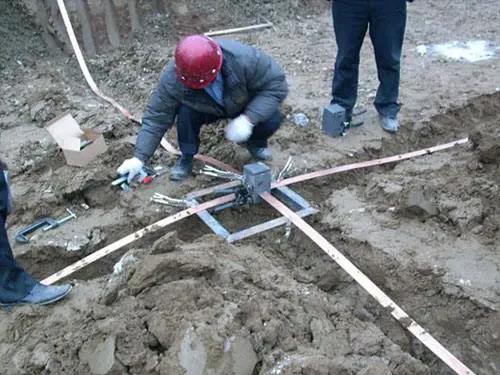
(1) The grounding conductor is generally made of 40mm×4mm galvanized flat steel.
(2) Use galvanized steel pipe or angle steel for the grounding electrode. The steel pipe should have a diameter of 50mm, wall thickness of at least 3.5mm, and length of 2~3m. An angle-steel size of 50mm×50mm×5mm is recommended.
(3) The top of the grounding electrode should be 0.5~0.8m below ground level to avoid the frozen-soil layer. The number of steel pipes or angle-steel electrodes depends on the soil resistivity around them and is generally no fewer than two, with a spacing of 3~5m between each.
(4) The grounding electrode should be more than 1.5m from a building and more than 3m from the grounding electrode of an independent lightning rod.
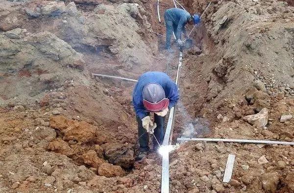
(5) The grounding conductor must be connected to the grounding electrode by a lap weld.
8. Methods for reducing soil resistivity:
(1) Before installing the grounding system, determine the resistivity of the soil around the grounding electrode. If it is too high, take the necessary measures to ensure that the grounding resistance meets requirements.
(2) Alter the soil structure around the grounding electrode. Within a 2~3m radius, mix in water-insoluble, highly absorbent materials such as charcoal, coke, cinders, or slag. This method can reduce soil resistivity to 15~110 of its original value.
(3) Use salt and charcoal to reduce soil resistivity. Tamp down alternating layers of salt and charcoal. Mix the charcoal and fine material evenly into a layer approximately 10~15cm thick, then add 2~3cm of salt; make 5~8 layers in total. Drive the grounding electrode into place after laying the layers. This method can reduce resistivity to 13~15 of its original value. However, salt is gradually washed away by flowing water, so it generally needs to be replenished once every two years or more.
(4) A long-lasting chemical resistance-reducing agent can reduce soil resistivity to 40% of its original value. The grounding resistance of electrical equipment should be tested once in spring and once in autumn each year, when there is relatively little rain, to ensure that grounding is compliant. A dedicated instrument is generally used for the test; the ammeter-voltmeter method may also be used.
9. Grounding inspections should cover the following:
(1) Whether connecting bolts are loose or corroded.
(2) Whether grounding conductors and electrodes below ground are corroded or have broken welds.
(3) Whether above-ground grounding conductors are damaged, broken, or corroded. For overhead incoming power conductors, including the neutral conductor, the cross-section must be selected as specified: aluminum conductors must not be smaller than 16 mm2, and copper conductors must not be smaller than 10mm2.
(4) To make the different purposes of conductors easy to identify, the phase conductor, functional neutral conductor, and protective conductor must each be distinguished by a different color. This prevents the phase conductor from being confused with the neutral conductor, or the functional neutral conductor with the protective neutral conductor, and helps ensure correct wiring of outlets. Use a three-phase, five-wire power-distribution system.
(5) Add a single-phase residual-current protector to the automatic air switch or fuse for the user’s power supply. Replace user wiring that is old and poorly maintained, has aged insulation, has an increased load, or has an undersized cross-section as soon as possible. This eliminates electrical-fire hazards and helps the residual-current protector operate correctly.
(6) For three-phase, five-wire equipment in a power system, the protective grounding conductor and neutral conductor must never have a cross-section less than 1/2 that of the phase conductor. In lighting systems, whether three-phase, five-wire or single-phase, three-wire, the ground and neutral conductors must have the same cross-section as the phase conductor.
(7) The functional-grounding and protective-grounding trunk conductors may be shared, but their cross-section must not be less than one-half of the phase-conductor cross-section.
(8) The grounding of each electrical device must be connected to the grounding trunk by its own separate grounding conductor. Several electrical devices requiring grounding must not be connected in series on one grounding conductor.
(9) For 380V distribution boxes, maintenance power boxes, and lighting power boxes, the cross-section of a bare copper grounding conductor should be >4 mm2, the cross-section of bare aluminum should be>6 mm2, the cross-section of insulated copper wire should be >2.5mm2, and the cross-section of insulated aluminum wire should be>4mm2.
(10) The grounding conductor should be 250–300mm above the ground.
(11) Paint the functional grounding conductor’s surface with alternating yellow and green stripes, paint the protective grounding conductor’s surface black, and preferably mark the equipment neutral conductor in light blue.
(12) Do not use flexible corrugated conduit, the metal cladding or mesh of pipe insulation, or the metal sheath of a cable as a grounding conductor.
(13) When welding a grounding conductor, use a lap weld. The lap length must meet these requirements: for flat steel, 2 times its width (with welding along at least 3 edges); for round steel, 6 times its diameter (with welding on both sides); and for a round-steel-to-flat-steel connection, 6 times the round-steel diameter (with welding on both sides).
(14) Copper and aluminum conductors must be secured to the grounding busbar with fixing screws; do not wrap them around it. When flexible flat copper braid is used as a grounding conductor, it must be an appropriate length and connected to the grounding screw using a crimped cable lug.
(15) While equipment is operating, operating personnel must check that the grounding conductor is properly connected to the grounding grid and electrical equipment, and that there are no breaks or other damage that reduces the conductor’s cross-section. Otherwise, treat the condition as a defect.
(16) During acceptance after equipment maintenance, the condition of the electrical equipment’s grounding conductor must be checked.
(17) The equipment department must inspect the grounding of electrical equipment regularly and promptly notify the responsible party to make corrections if problems are found.
(18) The grounding resistance of electrical equipment must be tested at intervals no longer than the specified inspection period, or during major or minor equipment overhauls. If a problem is found, analyze the cause promptly and take corrective action.
(19) The equipment department must test the grounding of high-voltage electrical equipment and grounding grids in accordance with the Code for Handover and Preventive Tests of Electric Power Equipment. The department responsible for the equipment must test grounding of low-voltage electrical equipment.
(20) For the short-circuit current entering the ground through a grounding system, use the maximum symmetrical-component value of the maximum short-circuit current flowing through the grounding system during an internal or external short circuit. Determine this current based on the system’s maximum operating configuration 5–10 years into the future, and account for the distribution of short-circuit current among the system’s grounded neutral points and the short-circuit current diverted through overhead ground wires.
10. The following equipment must be protectively grounded:
(1) Secondary windings of current transformers.
(2) Enclosures of distribution panels and control panels.
(3) Motor enclosures.
(4) Enclosures of cable-joint boxes and metal sheaths of cables.
(5) Metal bases or enclosures of switches and their operating mechanisms.
(6) Metal bases of high-voltage insulators and bushings.
(7) Indoor and outdoor metal wiring conduits.
(8) Grounding terminals of energy meters.
(9) Enclosures of electrical appliances and lighting equipment.
(10) Metal frames of indoor and outdoor distribution equipment and metal barriers around live parts.
11. Requirements for motor grounding:
(1) The motor grounding conductor should preferably be flat steel connected to the plant-wide grounding grid. If the grounding trunk is far away or installing flat-steel grounding conductors would detract from the appearance of the surroundings, use a natural grounding electrode wherever possible, or use flat copper wire as the grounding conductor.
(2) For a motor whose enclosure has a grounding screw, the grounding conductor must be connected to that screw.
(3) For a motor whose enclosure has no grounding screw, install one at an appropriate location on the enclosure and connect it to the grounding conductor.
(4) A motor enclosure that has reliable electrical contact with a grounded base does not need a separate ground. Grounding conductors should be installed neatly and attractively.
12. Requirements for distribution-panel grounding:
(1) The distribution-panel grounding conductor should preferably be flat steel connected to the plant-wide grounding grid. If the grounding trunk is far away or installing flat-steel grounding conductors would detract from the appearance of the surroundings, use a natural grounding electrode wherever possible, or use flexible copper wire as the grounding conductor.
(2) If bare copper conductor is used for grounding a low-voltage distribution panel, its cross-section must be at least 6mm2; if insulated copper wire is used, its cross-section must be at least 4mm2.
(3) For a distribution panel whose enclosure has a grounding screw, the grounding conductor must be connected to that screw.
(4) For a distribution panel whose enclosure has no grounding screw, install one at an appropriate location on the enclosure and connect the grounding conductor to it.
(5) A distribution-panel enclosure with reliable electrical contact to a grounding electrode does not need to be grounded separately.
13. How to inspect and measure a grounding conductor:
(1) Before testing, maintain a sufficient safe distance from the equipment under test to avoid accidentally touching live or rotating parts. Testing must be performed by two people.
(2) Before testing, select the resistance range on a multimeter, short the meter’s two probes together, and verify that the resistance-range reading is calibrated to 0.
(3) Connect one probe to the grounding conductor and the other to the equipment’s dedicated grounding terminal.
(4) If the equipment under test has no dedicated grounding terminal, place the other probe on the electrical equipment enclosure or a metal structure.
(5) Select the main grounding grid or a point reliably connected to the main grounding grid as the grounding point, and remove surface oxidation to ensure good contact.
(6) Read the value once the meter indication is stable. The grounding-resistance value must comply with the requirements of the applicable code.