
Xinya Classroom | Types of Impulse High-Voltage Dividers
A voltage divider is one of the main components commonly used in an impulse measurement system. Its function is to convert impulse high voltages of up to hundreds of thousands or millions of volts into voltages that can be measured by oscilloscopes and other recording instruments. Voltage dividers are mainly divided into three types: resistive, capacitive and resistive-capacitive dividers. 1. Resistive voltage dividers. Because of dynamic-response requirements, they should be designed to be as nearly non-inductive as possible.
A voltage divider is one of the main components commonly used in an impulse measurement system. Its function is to convert impulse high voltages of up to hundreds of thousands or millions of volts into voltages that can be measured by oscilloscopes and other recording instruments.
Voltage dividers are mainly divided into three types: resistive, capacitive and resistive-capacitive dividers.
- Resistive voltage dividers
Because of dynamic-response requirements, they should be designed to be as nearly non-inductive as possible. Using a resistive voltage divider as the conversion device under lightning impulse voltage conditions has several advantages:
-
When it is wound with resistance wire that has a low temperature coefficient, such as constantan wire, or with Karma wire, which has both a low temperature coefficient and high resistivity, it has good temperature stability and relatively good long-term stability.
-
A compact resistive-divider structure can potentially provide a relatively high response performance.
Because of these advantages, many standard measurement systems use resistive voltage dividers. However, they also have some drawbacks:
-
To achieve a high response performance, the resistance value cannot be too high. Since the divider loads the impulse voltage generator, connecting it shortens the impulse wave’s time to half-value. This can generally be addressed by adjusting the generator’s wave-tail resistor. For the same reason, resistive-capacitive dividers are difficult to use for measuring switching impulse voltage.
-
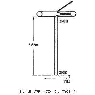
The error produced by a resistive voltage divider when measuring transient impulse voltages is related to the product of its resistance and stray capacitance to ground. Therefore, stray capacitance to ground and its effects should be minimized. The divider should also be made as nearly non-inductive as possible. For this purpose, Karma or constantan wire is wound closely in alternating directions on an insulating tube, with only a very thin sheet of insulating paper between layers, and then immersed in an insulating cylinder filled with transformer oil. This reduces the divider’s dimensions and stray capacitance to ground. A shielding ring is fitted at the top for compensation. Its structure is shown in Figure 1.
- Capacitive voltage dividers
Capacitive voltage dividers for measuring impulse voltages can be divided into two types. In one type, the high-voltage arm consists of multiple high-voltage capacitors stacked together; in the other, the high-voltage arm has only one capacitor. The first type is usually assembled from oil-paper pulse capacitors with insulating enclosures. These capacitors are required to have low inductance and withstand short-circuit discharge. A high-voltage oil-paper capacitor is assembled from multiple elements connected in series and parallel. Each element has not only capacitance, but also series inherent inductance and contact resistance, as well as parallel insulation resistance. Each element also has stray capacitance to ground. Such a divider must therefore be treated as a distributed-parameter system, hence the name distributed capacitive voltage divider, as shown in Figure 2. The second type has just one capacitor in its high-voltage arm, usually a pair of metal electrodes in a nearly uniform electric field, with air between the electrodes as the dielectric. It is a lumped capacitor and is therefore called a lumped capacitive voltage divider.
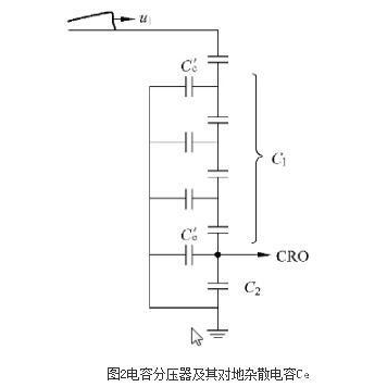
A distributed capacitive voltage divider has amplitude error but no waveform error. Its amplitude error can be completely eliminated by calibrating it with a standard voltage divider. However, when measuring steep-front waves, the capacitance of a capacitive divider is much greater than the stray capacitance of the shielding ring in a shielded resistive divider, so its response time is also much longer. For measuring steep-front waves, therefore, the response of a capacitive divider is inferior to that of a shielded resistive divider. A capacitive voltage divider consumes no energy and has no heating problem. For measuring waves with longer front times and times to half-value, a capacitive divider is more advantageous than a resistive divider. In addition, a capacitive divider can also serve as a load capacitor for adjusting the waveform.
The high-voltage arm of a lumped capacitive divider can use a standard capacitor filled with compressed gas. This type of capacitor has a very accurate and stable capacitance value and very low dielectric loss. Because it is shielded, its capacitance is not affected by surrounding objects. It has been used successfully in power-frequency measurements. However, when used as an impulse capacitive divider, it is prone to superimposed high-frequency oscillations.
- Resistive-capacitive voltage dividers
Resistive-capacitive voltage dividers can be divided by their connection into series and parallel types.
A parallel resistive-capacitive divider has difficulty damping stray oscillations in the divider circuit under fast lightning impulse voltage. It offers few advantages for measuring lightning impulse voltage and has been replaced by the series resistive-capacitive divider.
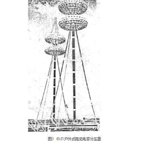
The series resistive-capacitive divider is also called a damped capacitive voltage divider. Many modern high-voltage dividers use this configuration. It overcomes residual inductance in the capacitive circuit, prevents divider oscillations and offers good performance. Depending on the value of the damping resistor used, series resistive-capacitive dividers can be divided into high-damping and low-damping capacitive dividers.
A high-damping capacitive voltage divider cannot also be used as the load (wave-shaping) capacitor for an impulse voltage generator; it is used only as a conversion device for measuring voltage. A low-damping capacitive divider has a very small series damping resistor. Its connection does not make it difficult for the test circuit to produce a standard wave, so it can also be used as a load capacitor and serves as a general-purpose divider. In terms of ease of use, it has more advantages than a high-damping capacitive divider; in terms of response characteristics, however, it is inferior because it still exhibits oscillation.
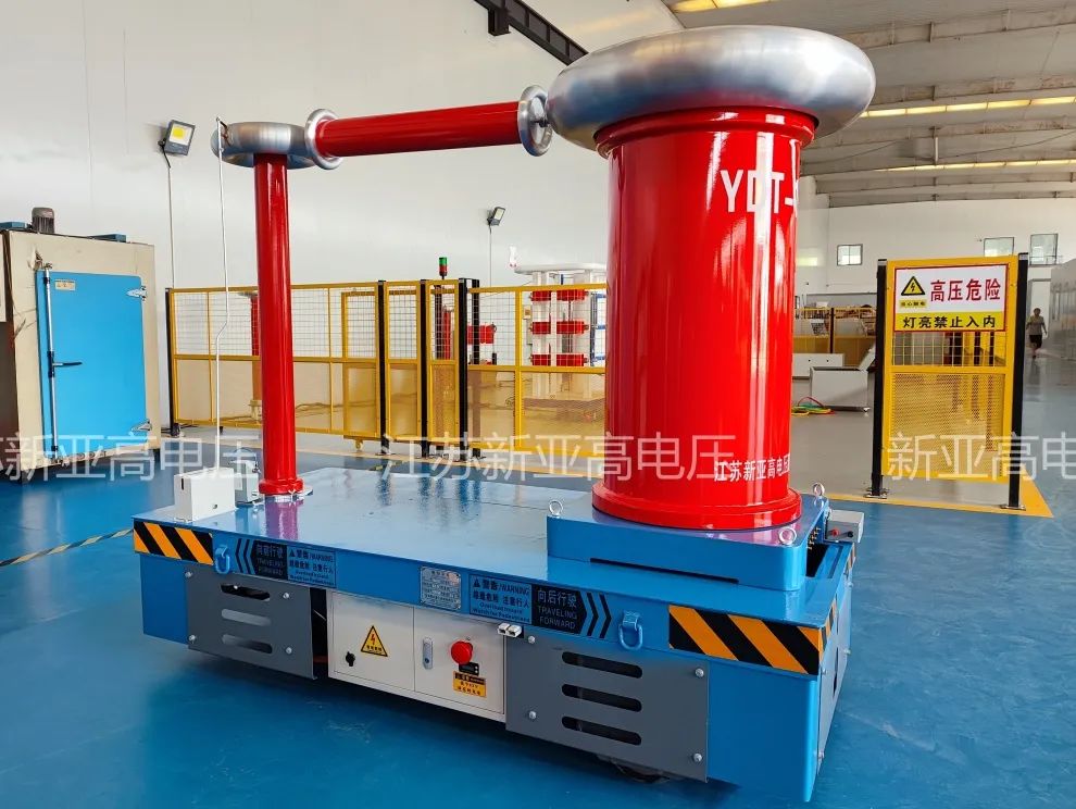
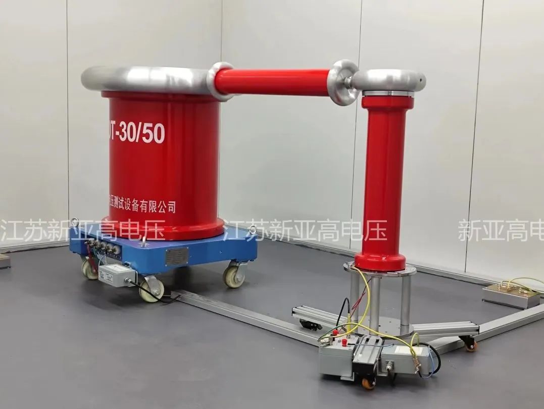
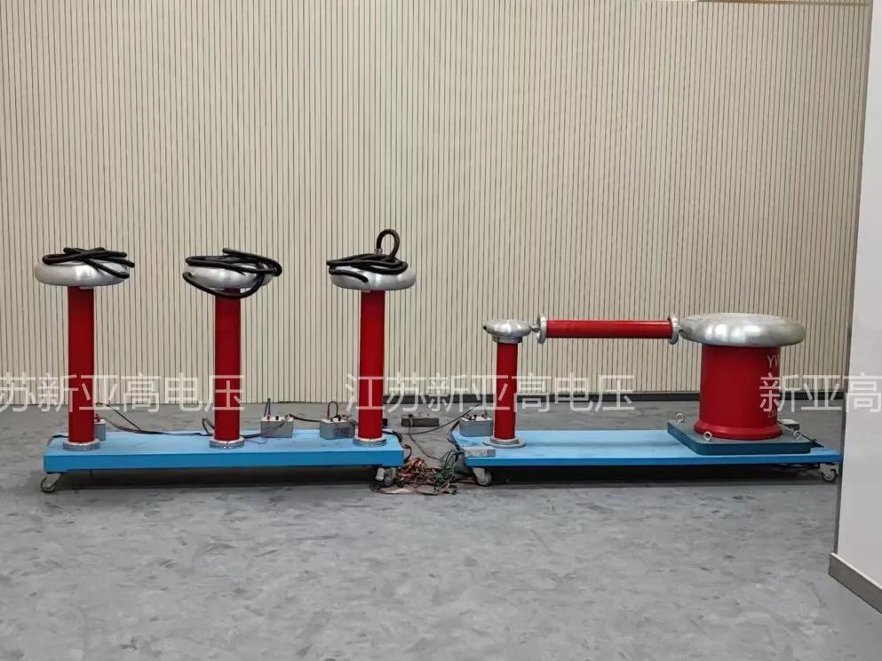
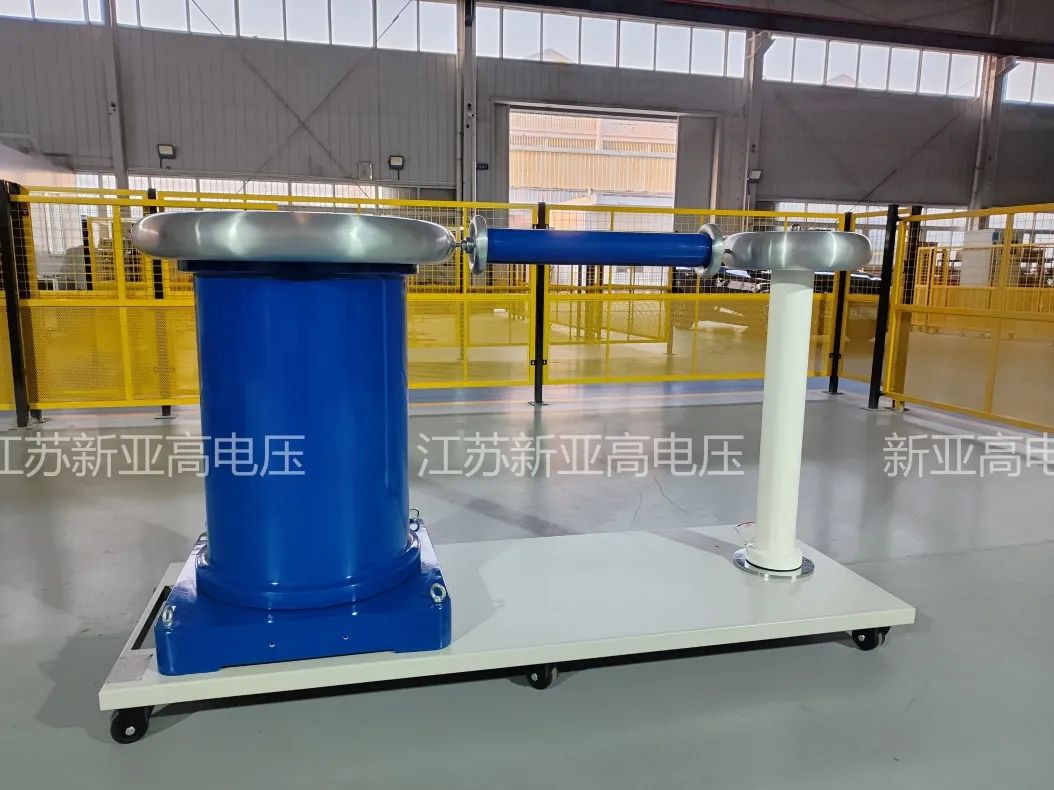
Jiangsu Xinya power-frequency test transformer + protective resistor + capacitive voltage divider