An Introduction to the Two-Station Digital Arrester Test System
This digital test system is used to verify the insulation level of arresters rated at 35kV and below under power-frequency high voltage. It can automatically perform power-frequency withstand-voltage, partial-discharge, and leakage-current tests. The system's measurement and control section runs in a Windows 10 environment and communicates via Ethernet.
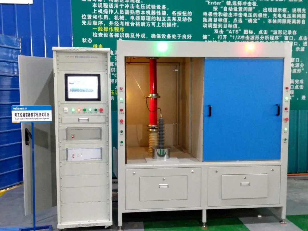
This digital test system is used to verify the insulation level of arresters rated at 35kV and below under power-frequency high voltage. It can automatically perform power-frequency withstand-voltage, partial-discharge, and leakage-current tests. The system’s measurement and control section runs in a win10 environment and communicates via Ethernet. Output voltage: 70kV; high-voltage current: 100mA; partial-discharge test range: 0.01~10npC; high-voltage test error: less than 0.5%; arrester total-current and resistive-current (peak and RMS) test error: less than 2.5%. The complete system consists mainly of two components: a digital control cabinet and a dual-station test-object operating cabinet. The control cabinet mainly provides partial-discharge detection, high-voltage raising and lowering, data-signal acquisition, and communications. The test-object fixture cabinet contains a partial-discharge-free test transformer, filter, current and voltage acquisition devices, signal-switching devices, test-object fixture racks, and other equipment. (The test-object fixture rack holds the products under test.)
System Features
-
The system has 2 shielded operating stations. Stations 1 and 2 can be interlocked and switched for power-frequency withstand-voltage and partial-discharge tests.
-
Test reports are generated automatically; the system includes a test-report generation function.
3. High test efficiency, suitable for rapid factory testing. While a test is running at the left station, a test object can be installed at the right station. As soon as the left-station test ends, the right station can begin testing immediately, while another test object is installed at the left station. Compared with the normal test process, this saves more than half the time.
-
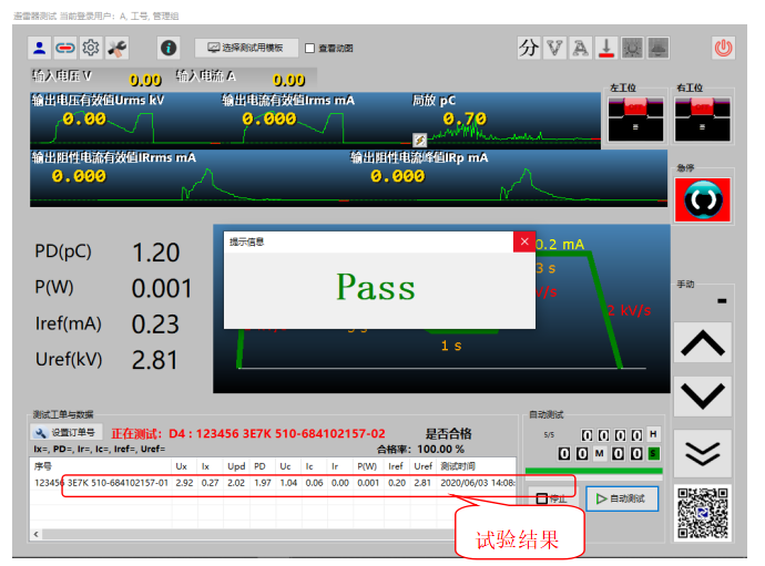
At the end of a test at each station, the system automatically determines whether the result is qualified, making it quick and easy to distinguish good products from defective ones.
-
The main circuit uses three-stage filtering, and the dual-station cabinet has a metal shield. These features effectively suppress spatial interference, reduce partial-discharge background noise, and meet the requirements for the test-space environment.
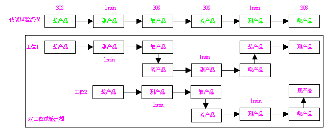
The efficiency improvement of the two-station test process is as follows:
Assume that loading and unloading a product each take 30S, and testing a product takes 1 minute. The traditional test process takes 4 minutes to complete tests on 2 products. With the two-station system, while one station is testing, a product can be removed from and another installed at the other station; 4 products can be fully tested in 4 minutes. This greatly improves testing efficiency: the capacity of the two-station system is 2 times that of the traditional test mode.
Control Console Software Overview
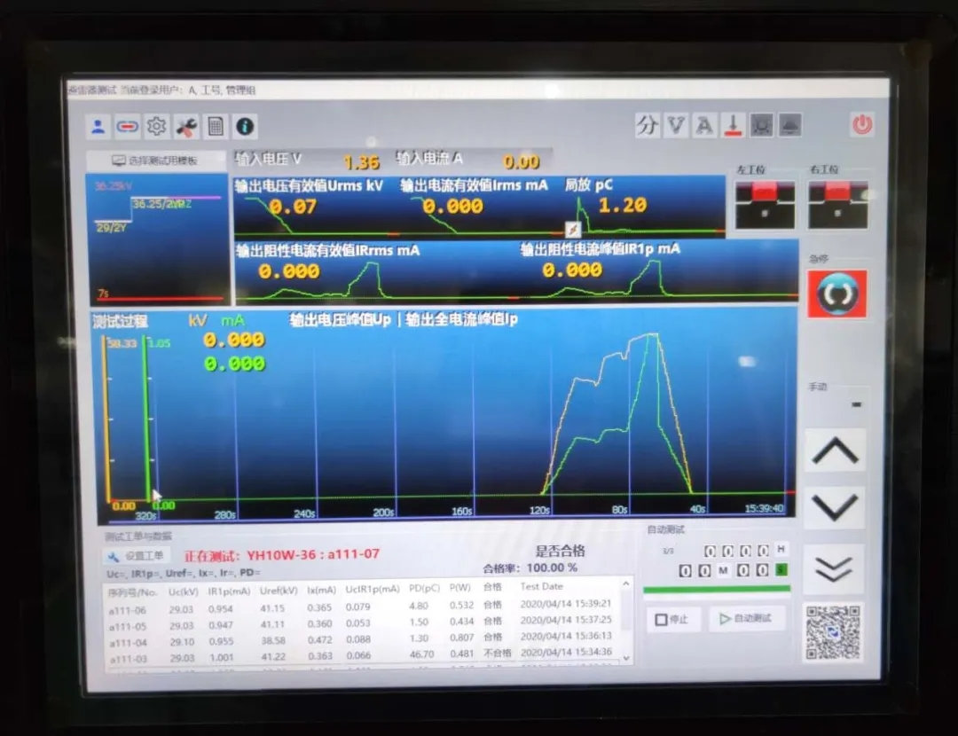
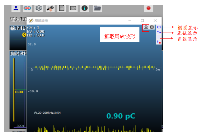
The control-console software interface is shown below. It mainly includes the test-system function area, status display area, software function area, test-template selection area, test work-order setup area, manual-test function area, and automatic-test function area.
Two-Station Shielded Operating Cabinet
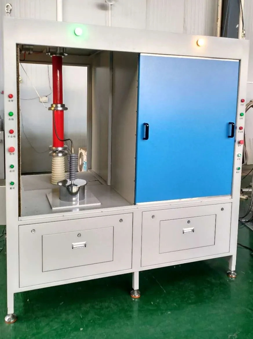
The partial-discharge-free coupling capacitor, which also serves as a voltage divider, the input unit, and the automatic grounding device are all installed inside the shielded operating cabinet. The partial-discharge-free protective resistor and high-voltage reactor are connected to the high-voltage terminal of the partial-discharge-free test transformer, which is placed on top of the cabinet, outside it. The output of the main circuit’s electronically adjustable power supply passes through the power filter on top of the cabinet and enters the operating cabinet, where it is connected to the input terminal of the partial-discharge-free test transformer. The high-voltage output (hose) cable can be extended to the test-object area inside the cabinet. A test-object fixture rack is installed in the middle of the cabinet to hold the products under test.