Xinya Classroom | Test Standards for Partial Discharge in Instrument Transformers
Partial discharge is often affected by many factors and has low reproducibility. As a result, errors in partial-discharge testing are much greater than in other high-voltage tests. To improve test accuracy, test personnel must strictly follow national standards.
Because partial discharge is often affected by many factors and has low reproducibility, errors in partial-discharge testing are much greater than in other high-voltage tests. To improve test accuracy, test personnel must strictly follow national standards.
Add the editor on WeChat: Annix_ich
Available free of charge
GB∕T 22071.1-2018 Instrument Transformers—Guidance for Testing—Part 1: Current Transformers.pdf
GB∕T 22071.2-2017 Instrument Transformers—Guidance for Testing—Part 2: Inductive Voltage Transformers.pdf
1. Test object and test conditions
The instrument transformer must be complete, or it must be fitted with all components that affect partial discharge. Moisture or contamination on the transformer’s insulating surfaces can cause partial discharge, so the surfaces should be cleaned before testing and kept clean and dry. After the instrument transformer is brought into the test area, it should be left to stand for a period of time until its internal temperature matches the ambient temperature. For oil-immersed instrument transformers in particular, the standing time should be at least 12h to eliminate bubbles in the oil caused by transportation.
To ensure accurate test results, the laboratory ambient temperature is generally kept between 5 and 40°C, and relative humidity must not exceed 85%. The test area must be large enough to account for the effects of nearby conductors on measurement accuracy. The spatial clearance around the test object should generally be at least 1.5 times the distance between its high-voltage and grounded parts, and metal conductors around the test object must be properly grounded.
2. Test voltage
The test voltage must be AC. The test voltage values (the pre-applied voltage and the measuring voltage) refer to the peak value of the AC voltage divided by √2. For an externally applied voltage, the test supply frequency is 45–55Hz. For self-excited induced-voltage testing, it must be 100–400Hz. The test-supply waveform should be close to a sine wave, with identical positive and negative half-cycles, and its peak-to-RMS ratio should equal √2 × (1 + 0.05).
3. Test procedure
Partial-discharge testing of an instrument transformer should be performed after all insulation tests are complete. During the test, first raise the voltage to the pre-applied value and maintain it for at least 10s. Then lower it to the measuring value and maintain it for at least 60s, and read the peak value of the partial-discharge pulses. Next, lower the voltage and disconnect the power supply. Calibrate the entire test circuit to obtain the partial-discharge quantity of the instrument transformer.
Partial-discharge testing may also be performed after a power-frequency withstand-voltage or induced withstand-voltage test. Lower the voltage to the measuring value, maintain it for at least 60s, and then take a reading to measure the partial-discharge quantity. If the measured value exceeds the value shown in Table 10, the test must still be repeated separately according to the procedure above, and the value obtained in this retest is taken as the partial-discharge quantity of the instrument transformer under test.
For a current transformer or a grounded voltage transformer, only one high-voltage terminal is connected to the high-voltage power system, so partial-discharge testing is needed only once. An ungrounded voltage transformer has two terminals connected to high-voltage terminals in the power system. During testing, high voltage must be applied in turn to each terminal of its primary winding, producing two readings. In addition, the two terminals of its primary winding must be short-circuited together and tested under high voltage, for a total of three readings. The highest value is taken as the partial-discharge quantity of the instrument transformer.
4. Permissible partial-discharge levels
Parameters characterizing partial discharge include apparent discharge charge, discharge repetition rate, average discharge current, squared rate, discharge power, partial-discharge inception voltage, partial-discharge extinction voltage and partial-discharge test voltage. For instrument transformers, apparent discharge charge (q) is the preferred parameter for routine factory testing. The permissible apparent discharge charge (q) for instrument transformers is listed in Table 10.
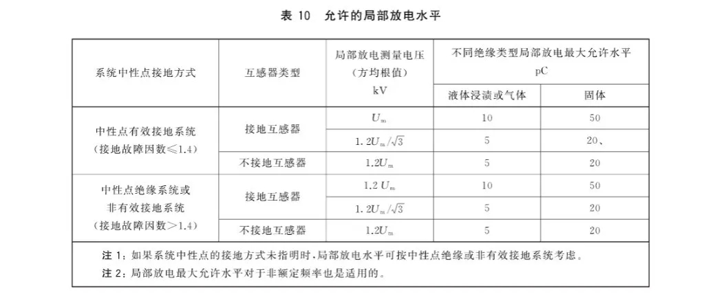
Permissible partial-discharge level for voltage transformers ↑
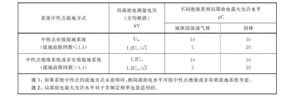
Permissible partial-discharge level for current transformers ↑
Add the editor on WeChat: Annix_ich
Available free of charge
GB∕T 22071.1-2018 Instrument Transformers—Guidance for Testing—Part 1: Current Transformers.pdf
GB∕T 22071.2-2017 Instrument Transformers—Guidance for Testing—Part 2: Inductive Voltage Transformers.pdf
In the next issue, we will discuss how to perform partial-discharge testing on instrument transformers.