Xinya Classroom | An Introduction to the Various Waveforms of Impulse Voltage Generators
An impulse voltage generator is a high-voltage generator that produces pulse waves. It is used to study the insulation performance of electrical equipment subjected to atmospheric overvoltages (lightning). The destructive effect of an impulse voltage depends not only on its waveform and amplitude, but also on its waveform steepness. Current impulse voltage generators in China can produce eight types of impulse waveforms. Here is a brief introduction.
An impulse voltage generator is a high-voltage generator that produces pulse waves. It is used to study the insulation performance of electrical equipment subjected to atmospheric overvoltages (lightning). The destructive effect of an impulse voltage depends not only on its waveform and amplitude, but also on its waveform steepness. Current impulse voltage generators in China can produce eight types of impulse waveforms. Here is a brief introduction.
GB311, Insulation Coordination for High-Voltage Transmission and Distribution Equipment—High-Voltage Test Techniques, specifies three standard impulse waveforms:
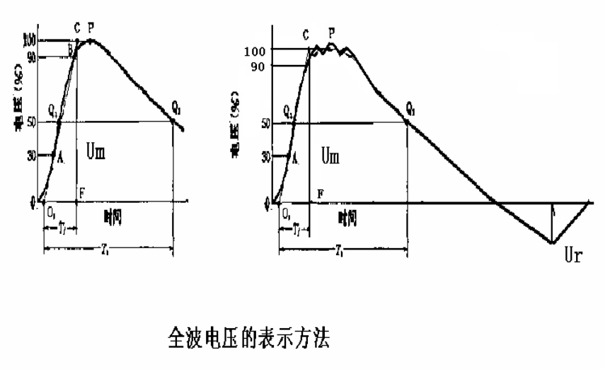
(1) Standard 1.2/50-microsecond full lightning impulse, as shown in figure a;
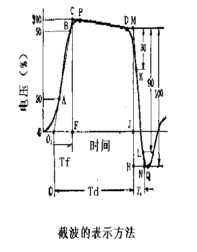
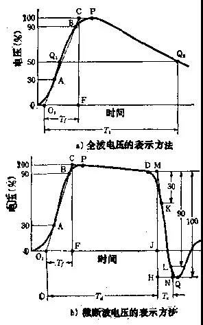
(2) Standard 1.2/2~5-microsecond chopped lightning impulse, as shown in figure b;
Zero-crossing coefficient: 0.25-0.35;
(3) Standard 250/2500-microsecond switching impulse;
Tf = 20~250uS; duration at 90% ≥200uS
Zero-crossing time ≥500uS
IEC517 specifies two standard impulse waveforms for on-site impulse testing of GIS (gas-insulated switchgear):
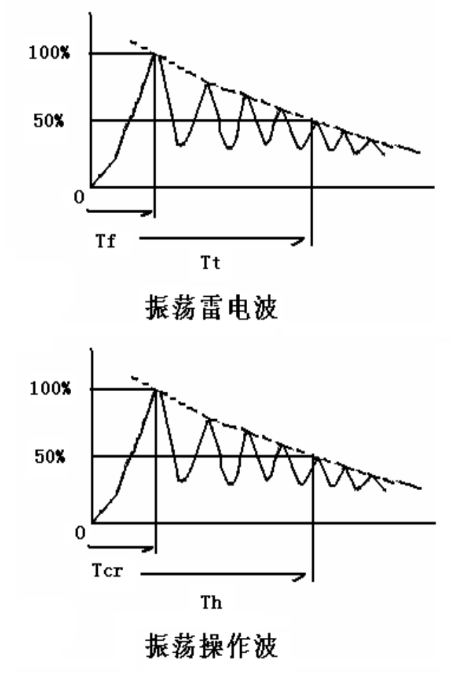
(4) Oscillating lightning impulse with Tf<15 microseconds;
(5) Oscillating switching impulse with Tcr>100 microseconds;
The two waveforms are shown below:
DL/T557, Steep-Front Impulse Withstand Test for Insulators for High-Voltage Lines, specifies the standard impulse waveform for steep-front impulse withstand testing of line insulators:
(6) Steep-front impulse with Tf=100~200 nanoseconds and a steepness of 2500kV/uS; maximum output voltage amplitude 500kV. It is suitable for steep-front impulse withstand testing of Type B insulators for high-voltage lines;
JB5892, Technical Conditions for Organic Composite Insulators for High-Voltage Lines, specifies the standard impulse waveform for steep-front impulse withstand testing of organic composite insulators:
(7) Steep-front impulse with a steepness greater than 1000kV/uS and a maximum output voltage amplitude of 600kV. It is suitable for steep-front impulse withstand testing of organic composite insulators for high-voltage lines.
DL474.6, Induced Withstand-Voltage Test of Transformers Using Switching Waves, specifies the standard impulse waveform for the transformer switching-wave induced withstand-voltage test:
(8) Switching-wave impulse with Tcr>100 microseconds, Tz>1000 microseconds, and Td(90)>200 microseconds.
Suitable for switching-wave induced withstand-voltage testing of power transformers.
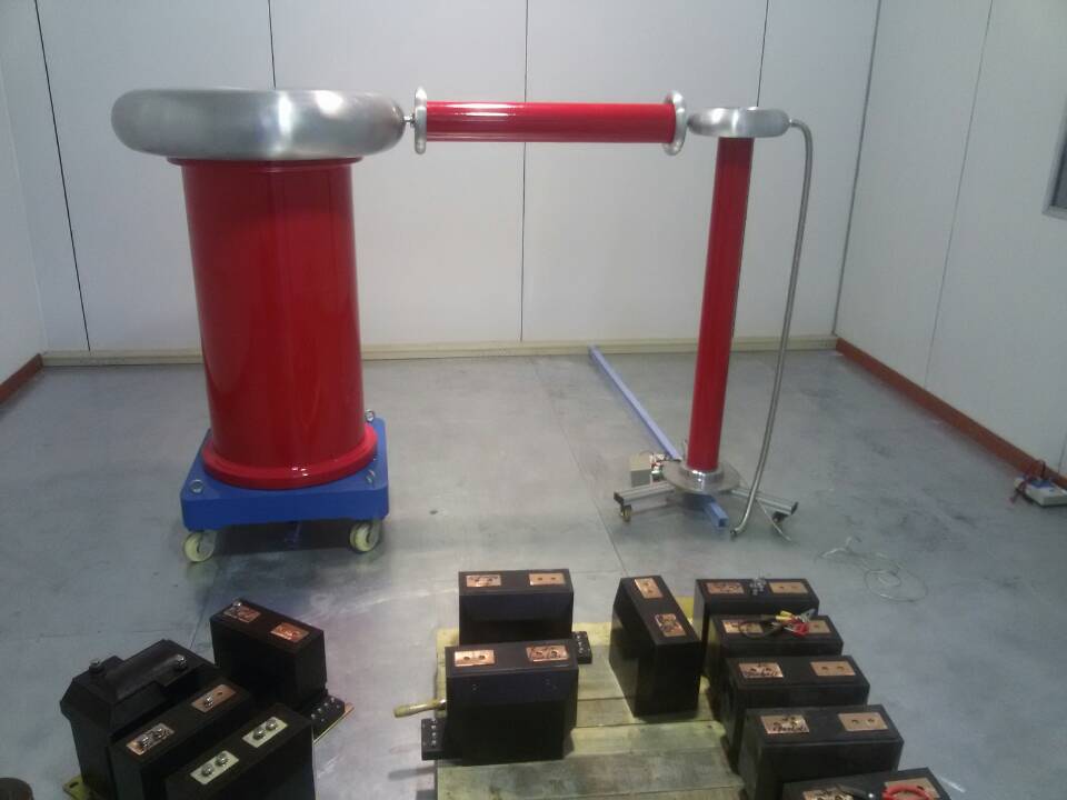
Our company’s impulse voltage generators are primarily used to produce standard full lightning impulses and chopped lightning impulses.
Standard full-wave requirements:
(1) Wavefront time Tf is 1.2uS, with a permitted tolerance of ±30%;
(2) Time to half-value Tt is 50 uS, with a permitted tolerance of ±20%;
(3) Test voltage Um has a permitted deviation of ±3%; this refers to the difference between the specified value and the measured value, not the measurement error.
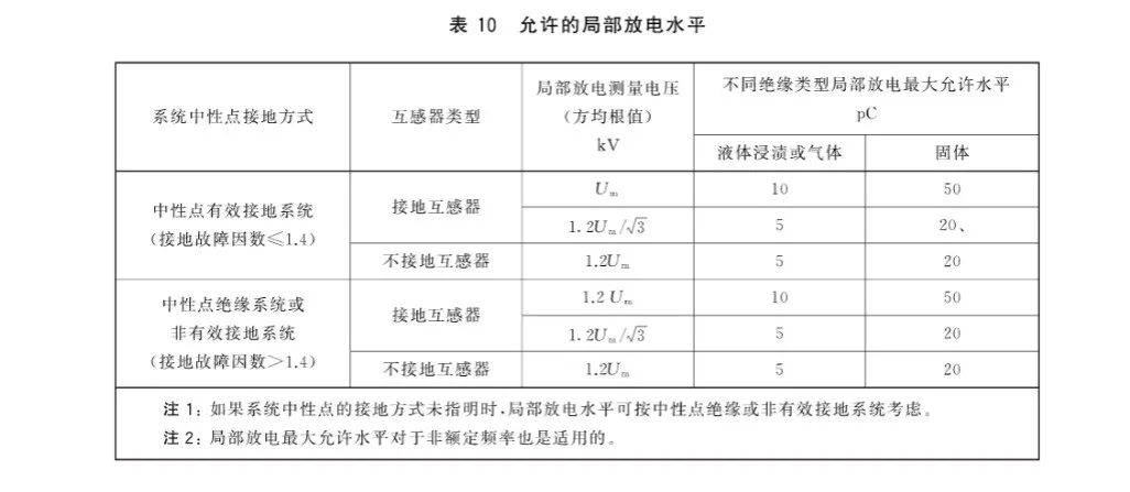
(4) If the actual waveform has oscillation (overshoot) in the wavefront and damped oscillation crossing zero at the tail, the oscillation amplitude must not exceed 0.05Um, and the amplitude of the damped-oscillation rebound wave must satisfy Ur/Um<0.5.
How to draw the waveform:
The line joining the points at 30% and 90% of the crest value intersects the horizontal axis at the virtual origin O1. The distance from this point to the vertical line through point C, where the above line intersects a parallel line, is the wavefront time Tf. The distance between O1 and the vertical line through the half-crest point on the wave tail is the wave-tail time Tt. T1=1.67T
Chopped-wave requirements:
(1) Wavefront time Tf is 1.2uS, with a permitted tolerance of ±30%;
(2) Chopping time Td is 2~5 uS;
(3) Test voltage Um has a permitted deviation of ±3%; this refers to the difference between the specified value and the measured value, not the measurement error;
(4) If the actual waveform has oscillation (overshoot) in the wavefront, the oscillation amplitude must not exceed 0.05Um; the rebound-wave amplitude Ur/Um zero-crossing coefficient is specified as 0.25-0.35;
How to draw the waveform: The line joining the points at 30% and 90% of the amplitude of the reverse peak at point D intersects the reverse peak at N, and intersects the horizontal line through point D at M. The distance between O1 and the vertical line from point M to the horizontal axis is the chopping time Td. T1=1.67T